During the Meeting
“Easy Mode”
If you just want to show a wide camera shot and be done with it, this is the section for you.
Chambers
There are three rows of buttons with labels on the Switcher Controller
Press the first button (from the left) on the middle row (see Fig. 11)
It should now be lit in red and you should see the camera on the top right window of the MultiView Monitor
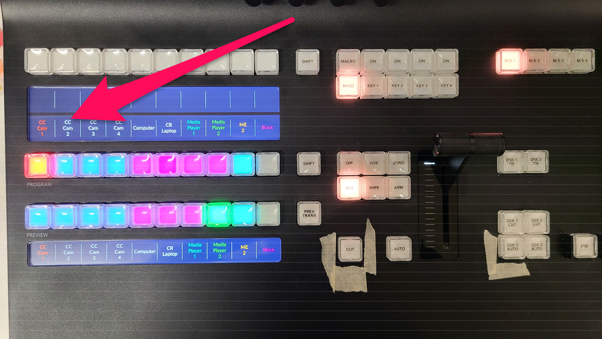
Fig. 11 Easy Mode Switcher
Multi-Purpose Room
If the meeting is in the Multi-Purpose Room, you’ll need to do a couple of things..
Cameras
There are three rows of buttons with labels on the Switcher Controller
Find the button on the right side of the middle row that says
SHIFT(see Fig. 11)Hold down the
SHIFTbuttonYou’ll notice the labels on the buttons change to
MP Cam 1,MP Cam 2, etc.
Press the first button (from the left) on that same row.
It should now be lit in red and you should see the camera on the top right window of the MultiView Monitor
That was pretty easy, but we haven’t gotten to the audio part.
Audio
Access the UCI interface by following the steps shown in the Routing Section.
Once the page loads, you should see a screen similar to the one shown in Fig. 7.
In the “Control Room Audio Source” section, select between “Chambers” and “Multi-Purpose Room” using the two buttons.
You will also need to unmute the “WLS-2” channel as shown in Audio to send audio to the video system.
See Fig. 7 for details.
Note
If this is all you want to do, you can skip to the section titled After the Meeting.
Advanced Mode
Warning
This section is for those who want to get a little nerdy 🤓
Switching Video
Your main area of focus is the left MultiView Monitor. You should see two large windows at the top and eight small ones below.
The top two are “Preview” and “Program” (respectively). “Program” is what you’re sending out (live, on-air, etc) and “Preview” can be thought of as “what you want to send next”. These are also referred to as buses (Program Bus and Preview Bus).
The buttons on the Switcher Controller allow you to select what goes to each bus.
They also light up to indicate what’s selected. This is called Tally.
The green tally shows what’s on preview and the red tally indicates what’s going to program.
You’ll also see the borders on the MultiView Monitors following the same convention.
The bottom row controls the Preview Bus and the next row up controls the Program Bus.
Typically you want to select a source on preview then take it “live” using either the
CUT or AUTO button found to the left of the “T Bar”.
CUT performs a direct cut (self-explanatory) and AUTO will do a dissolve transition (or “fade”).
Afterwards, whatever was on preview goes over to program and vice-versa.
This is where the Tally indicators come in handy.
Layout (Chambers Cameras)
The cameras for council chambers are mapped to sources 1-4 on the Switcher Controller (labeled
CC Cam 1(2, 3, 4))The computer input (Dais laptop / Podium) is mapped to source 5 on the switcher (labeled “Computer”) and its preview can be found on the right MultiView Monitor
Layout (Multi-Purpose Room)
The cameras for the multi-purpose room are mapped to a second “layer” on the switcher.
To change layers, find the SHIFT button directly to the right of the “Program” row
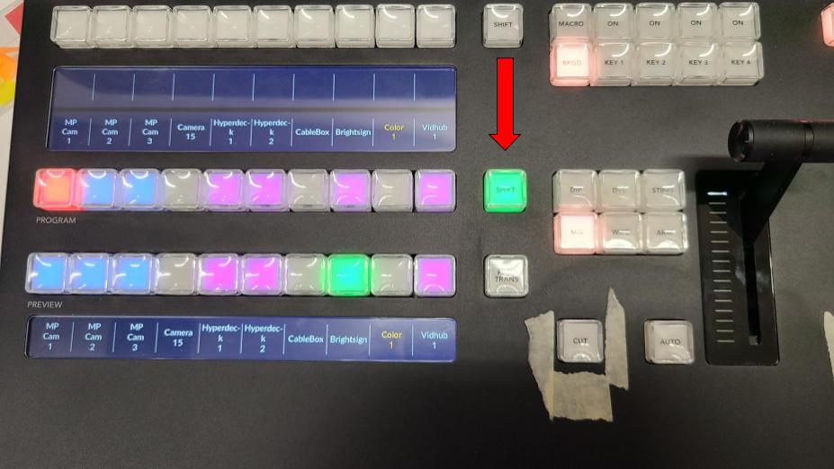
Fig. 12 Shift Button
You can press and hold SHIFT to temporarily use the second layer,
or double-tap it to toggle between the two layers.
While the second layer is active, the SHIFT button will be lit in green.
The multi-purpose room cameras will then be on the first three source buttons (labeled MP Cam 1 (2, 3)).
Note
When I run things, I sometimes use a separate “profile” in the Switcher Controller to make it a little easier when going between the MP Room and chambers. That may be a bit beyond the scope of this document though.
Camera Control
The Camera Controller on the right handles all seven cameras, but obviously only one at a time. To select which camera you want to control, use the selection buttons (numbered 1 through 10 below the touch screen).

Fig. 13 Camera Controller Overview
The button for the currently selected camera will be (in most cases) lit in amber (aka orange). It’s also shown on the screen (top-left).
Sometimes, you’ll notice the selected camera button change to red. This just means that camera is currently “live” on the Program Bus (more Tally goodness).
The cameras for council chambers are mapped to buttons 1-4
The MP Room cameras are on 6-8
The ordering for both sets of cameras is identical to the switcher and multi-view monitor (for obvious reasons)
Note
The estute among you may have noticed that we skipped number 5. That’s intentional since it’s easier to have them on separate rows.
Touch Screen Views
On the screen you should see one of two layouts shown in Fig. 14.
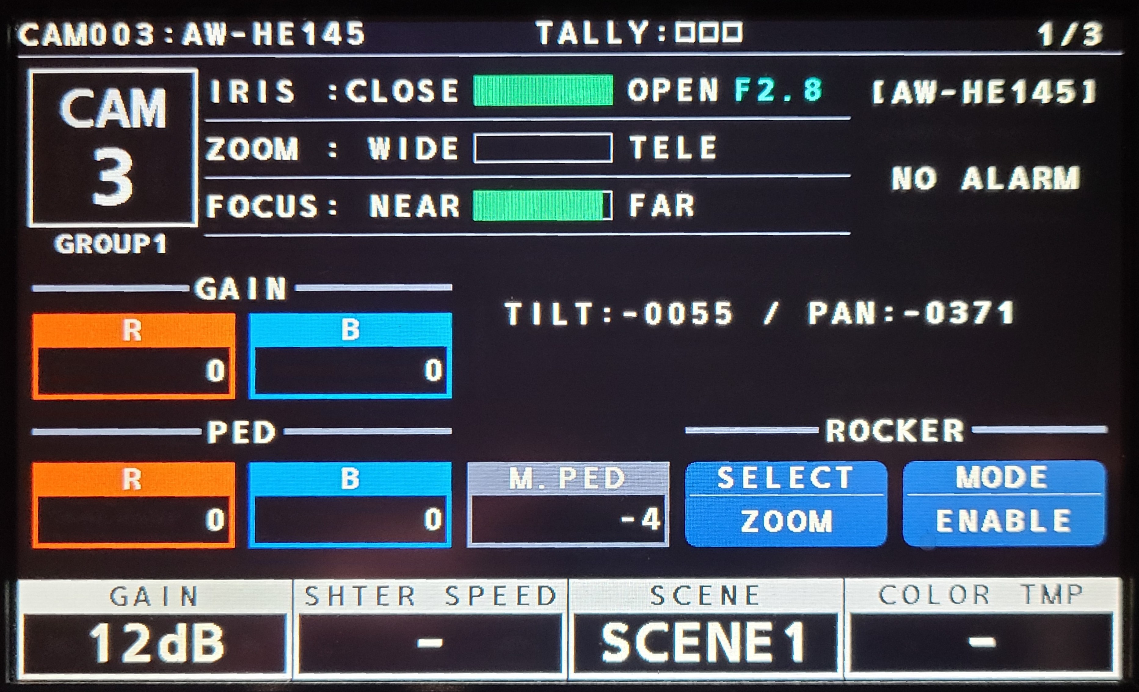
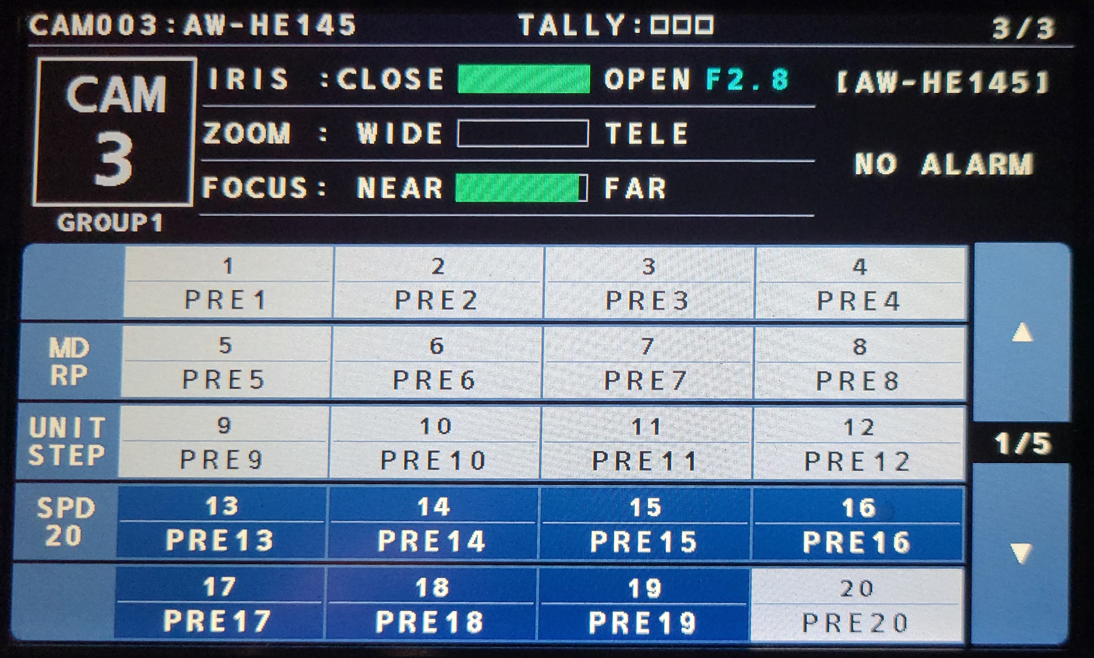
Fig. 14 Camera Screens
Since you’ll probably just want to use presets, you can get to the Preset Screen (the right image above) using the Up/Down triangly-looking buttons to the right of the touch screen. They are physical buttons lit in yellow (shown in Fig. 15).
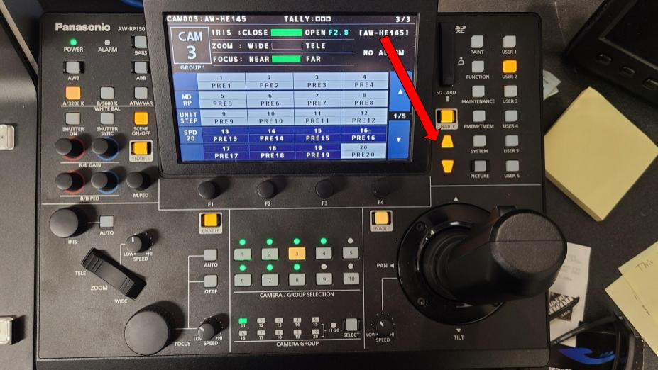
Fig. 15 Navigation Buttons
Presets
Once in the Preset screen, you can recall the desired preset for the selected camera using the buttons on the touch screen. The current preset layout is:
Chambers
Camera 1
PRE 1is the “go-to” wide shot I use
Camera 2
PRE 1is a tight shot of the “Mayor” position
Camera 3
PRE 1throughPRE 10are tight shots for each position on the Dais (from left to right)PRE 11andPRE 12are the two positions on either side of the Dais (Assistant Secretary and Assistant City Manager respectively)PRE 20is a backup wide shot in case I have camera 1 planted somewhere else
Camera 4
PRE 1is a good starting point for the podium shot (may need adjusting depending on the person’s height)
MP Room
All cameras (5, 6, 7) just have
PRE 1set up as a starting point. 🤷